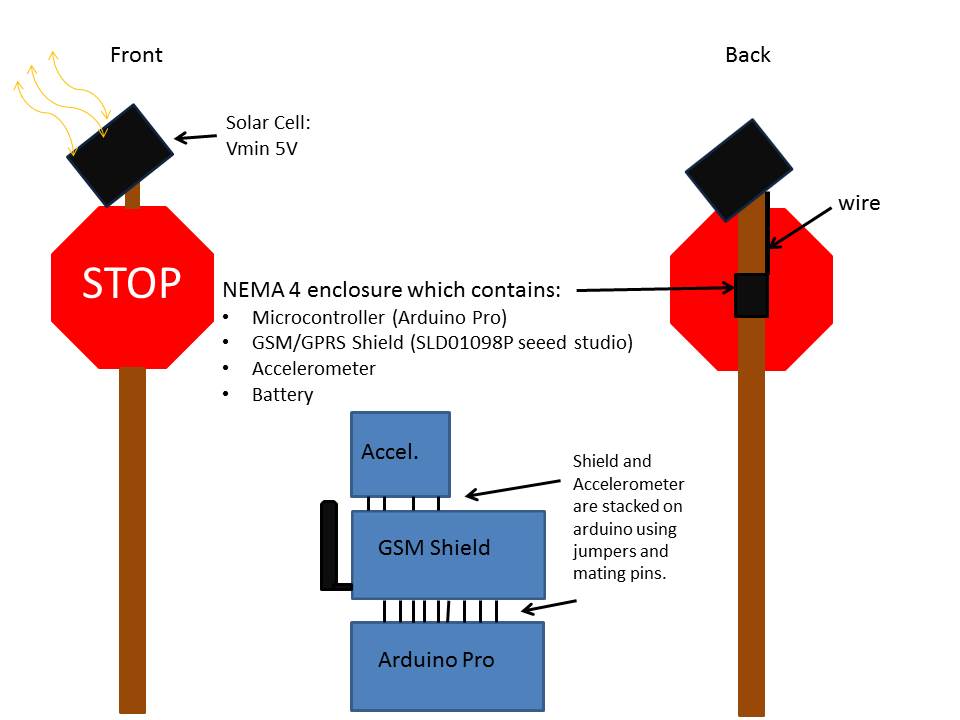
Design Sketch
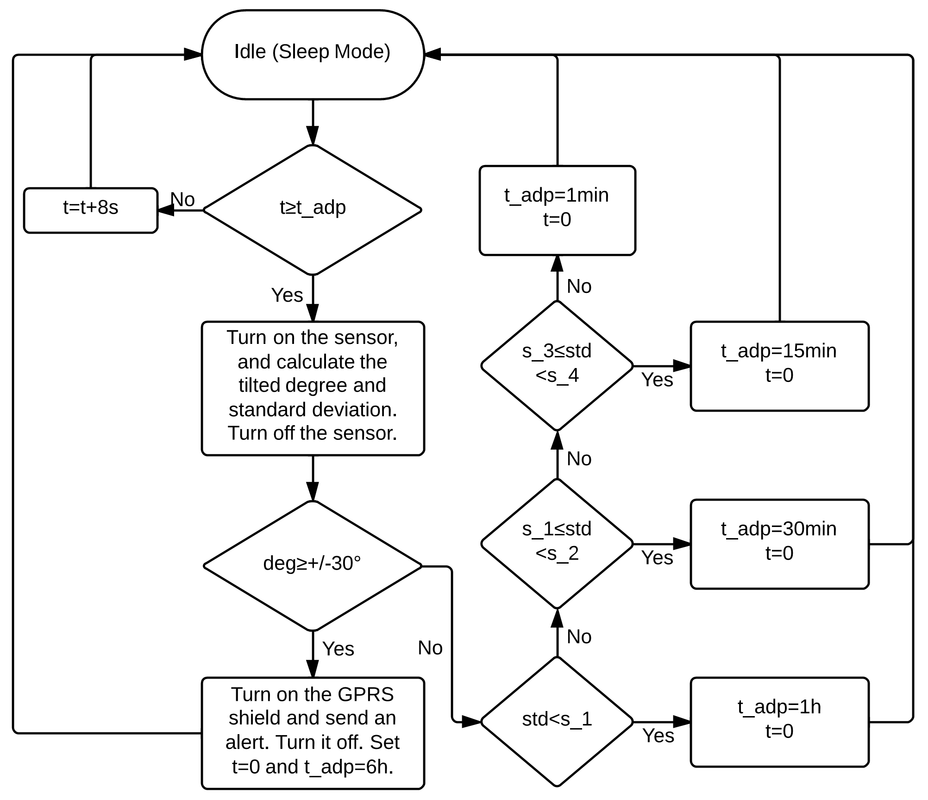
Embedded Program
- The tracking system has an adaptive duty cycle to be efficient.
- When the measurement is not needed, the system will go to its sleep mode.
- In the sleep mode, the sensor (accelerometer) will be in the standby mode which is best status to save power. The Atmega328 will go to its sleep mode with only a “watchdog” timer on in order to calculate time for the duty cycle.
- The GPRS shield will be turned on only when a message needs to be sent out because the shield consumes a lot of power (1W) when working.
- To change the duty cycle is based on the standard deviation of the measured tilt degrees which is influenced by the wind speed.
Power Supply System
The power supply system consist of a 7.2 V flexible solar panel, 5V Regulator/Charger Module w Li-Ion Battery, connected to the rest of our communication system (Arduino, accelerometer, and GPRS shield). The solar panel will connect to the charging circuits which will output to the Li-Ion battery and the communication system. The module provides a regulated 5V DC (300mA) output via screw terminals to power the communication system.
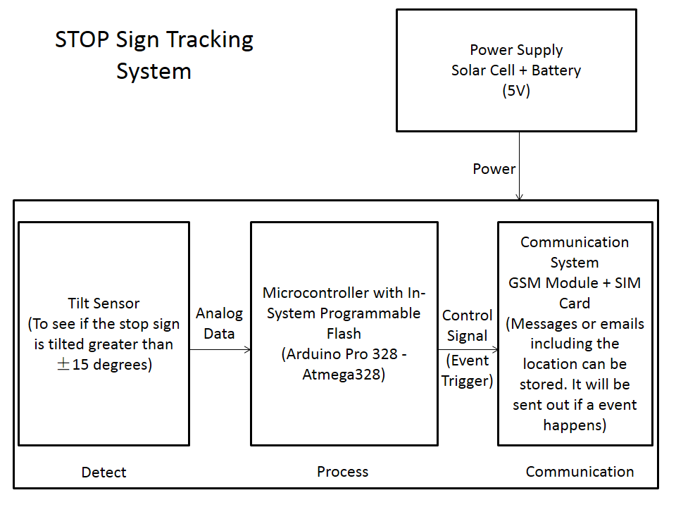
Design Overview
Current design consists of four parts:
- System Management: Used to combine the system monitoring and communications.
- System Monitoring: Monitors the current state of the critical stop sign. Based upon the tilt of the sign.
- Communications: Used to send out alerts to the end-users which will reduce response time to a broken sign.
- Power: Harvest energy (solar), Store excess energy, and supply energy to monitoring/management system.
Final Project Design Sketch