Kalman Filter
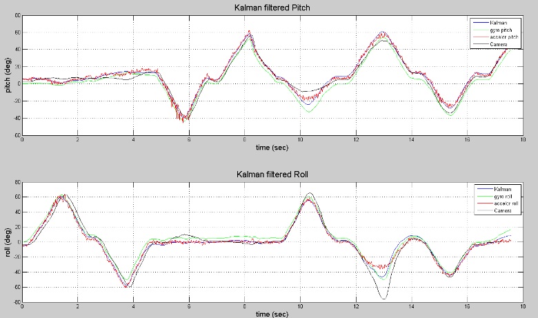
The Kalman filter is a real-time algorithm that calculates a very good estimation of the orientation of the quadcopter based on accelerometer and gyroscope data. Since the gyroscope tends to drift over time and the accelerometer is inherently noisy, neither one of these sensors will provide a very good orientation when used alone. The Kalman filter is able to mitigate the weaknesses of each sensor and combine the two to provide a very good estimation of the orientation.
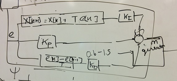
The algorithm used by the Kalman filter starts with a prediction of the quad's state variables and uncertainties for the next point in time. Then a comparison is made between the prediction and an actual measurement at the time point, and an estimation of the state variables and uncertainties is computed using a weighted average filter. This estimation is is then used as the input and prediction for next measurement and continues on indefinitely. Proper weights of each sensor's certainty, along with other system variables, were defined through experimentation.
- ______________________________________________________________________________________________________________________________________________________________
Lightweight Filter
This filter is based on the Kalman filter, but involves less math and usually termed a "good enough" filter. Orientation can determined based on accelerometer or gyroscope data. Similar to the Kalman filter, the lightweight filter combines the data from the two sensors to get a more accurate reading as seen in Figure 2 and described below.
Starting with the gyroscope, data is input as degrees/second and by measuring over a period of time, the angle of change about an axis can be determined in degrees. The gyroscope approximation still needs a starting point, which comes from the accelerometer for only the first reading. The overall orientation about any axis for gyroscope reading is then initial accelerometer angle plus the summation of degrees changed from gyroscope at each measurement. The angles are then converted into a unit vector.
The measurements from accelerometer don't rely on previous measurements. A vector is created from the accelerometer data which measures gravity. The two vectors are combined by weighting them together. The more accurate of the two having a larger weight. The vector can then be converted back into angles for orientation.
![]()
- ______________________________________________________________________________________________________________________________________________________________
Motor Signal-Mixer
To control the quad the same way the GU344 did, motor signal-mixer takes in flight controls of throttle, pitch, roll, and yaw and adjusts the signals for each motor. The flight controls are set as percentages from 0 to 100%. Throttle starts at 0%, whereas pitch, roll, and yaw all start at 50% to prevent rotation about an axis. Going down to 0% will cause movement in one direction and 100% is movement in the opposite direction.
The motor output is also set as a percentage from 0 to 100%. 0% represents the baseline duty cycle for the PWM to the ESC and the motors being off. 100% is the maximum duty cycle that has been set and is the fastest the motors will spin.
All changes in pitch, roll, and yaw require the quad to remain at the same altitude, so the mixer takes in throttle exactly as it is and spins some motors faster and other slower than throttle to achieve the command. As for the other flight controls, their values must be adjusted in the mixer. 50% means no movement for them, so 50 is subtracted from every one of those commands. The output for each motor is then
Throttle ±(Pitch-50)±(Roll-50)±(Yaw-50)
Each flight control that requires rotation is either added or subtracted based on the location of the motor on the quad.